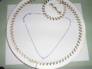
As a preliminary project, I decided to make a spirograph. Not a mini, notepad sized one, for a fine tipped pen. A chunky, full sheet of paper kind, for a Sharpie.
As a first attempt, I used Inkscape's render function to generate gears. The number of teeth is self-explanatory, the circular pitch ends up affecting the radius. I used 37, rather arbitrarily. It turns out i just barely made the gear big enough for a 1/8 inch cutter to cut it out, so it was a good guess on my part. Its worth noting that its quite important to pay attention to this - you need to scale all your gears the same if they are to mesh, so if you forget, you will have to work it out tediously by measuring and dividing.
The existing Foulab CNC chain was QCad for drawing, gCNCCam for generating the G-code, and EMC2 for controlling the machine. Inkscape saves to DXF, which can be loaded by QCad so I loaded my gear directly there. The center is not indicated by Inkscape, but is easily found geometrically, as shown.
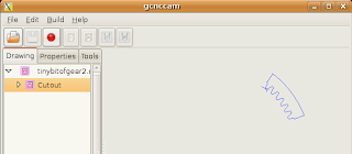
gCNCCam has some problems generating a proper entry move, so we use a modified version, available here.
I put a central hole to act as an axis, and a couple others to act as placement points for a Sharpie. I then drew a large outer gear ring, which would be treated as the outer ring gear. It was so large, i had to cut it into two parts, to fit on the CNC. I tottled off to the lab to cut it.
Total fail. EMC2 refused to cut it, and rightly so, since the tool radius was such that many of the corners could not be cut out. No concave corner can be tighter than the tool radius. Unfortunately, gCNCCam doesn't complain about this, and its processing for a file of this complexity was very slow.
I manually edited the drawing, to round out the bottoms of the gears. This process quickly became iterative, and slow. Heres my advice:
- Cut out a small piece of gear, gCNCCam will work much faster, and if it will cut one tooth, it will cut them all. However, bear in mind that:
- If the G-Code fails, look closely at where. When I chopped my gear into parts, it was the point where I chopped it that had a tiny concavity, not the tooth itself. Putting a small round on that corner resolves the problem.
- Numerical issues can also cause problems. I've had better luck designing the drawing for a tool with 3.2mm diameter, and telling EMC2 that the tool diameter was 3.199mm.
- The gCNCCam to EMC2 loop quickly gets tedious, and at first, I was doing the drawings at home, and then heading to Foulab to discover that EMC2 would reject them. Loading the file in gCNCCam can also be very long. (It seems to do all its work on load, or when a parameter is changed, analyzing the graph then. Clicking the generate GCode button is anticlimactic, and takes only a moment.)
- The solution I found was to install a virtual machine with the EMC2 distro, and run the design through at home, before heading to the CNC. The boring wait for processing could be offset by working on other things.
Its also worth noting, that gCNCCam got inside and outside backwards on the drawing. So my first attempt at the ring gear had the tool on the inside, with, needless to say, poor results. gCNCCam draws an arrow in the direction of cut. If your template is for counter clockwise, but it draws the arrow clockwise, switch the tool from inside to outside.
So after much hand editing, I got it to work. I cut the gears out of MDF, which can be cut pretty fast, and even then, the cutting time was LONG, over an hour for the ring gear.
I cut out a 24 tooth inner gear and a 72 tooth outer gear, glued some legs on and got down to drawing. And this is where those of you who kept reading to the bottom of the post get to laugh at the author. Thats right - 72 and 24 - so it draws:
 |
| Since 72/24=3 i get a lovely triangle |
Twenty-five and 27 tooth inner gears will be coming up shortly, don't worry. After this, however, I will probably write my own gear drawing code. The Inkscape renderer looks good, but it has too many concave corners that have to be hand edited.


No comments:
Post a Comment