Sunday 20 March 2016

Art?

Recently I became altogether too interested in a code golf problem that was posted on stackexchange. The problem was to develop a program to draw Van Gogh's starry night using a program of maximum length 1024 bytes. The winning programs used existing image compression algorithms, which makes logical sense, but was somehow aesthetically unsatisfying. The originator reposted a challenge to come up with an optimization based approach, that beat the existing non-off-the-shelf compression approach. The problem is particularly interesting to me because I like algorithms for drawing. The above image is the result I came up with. The original, of course, looks like this:


This took a long time. I chipped away at it for a while, got distracted, poked at it periodically - these optimizations take a long time to run - but finally managed to beat the existing top score for non-off the shelf compression. Here's what I said on Stack Exchange, and then a bit more detail on a few points.

Everybody has probably forgotten about this problem by now, except me....

This problem interested me far too much, especially as it quickly became apparent that approaches using image compression algorithms were definitely in the lead, but yet somehow unsatisfying from an aesthetic standpoint. Approaches based on optimizing a set of drawing primitives were somehow more pleasing from a code aesthetic point of view, but seemed blocked just above the 5000 score.

Nneoneo's method that did not use an off the shelf image compression beats the 5000 mark, but does so by encoding a tiny image and upscaling it.

Here is a program that uses drawing primitives only, is generated automatically by an optimization method, and manages to get a score of 4749.88.

[Edit: snipped for brevity, but available here]

It uses a number of tricks used previously here:
  • Using a blur to push the final score up a bit
  • Cramming raw bytes into python code (which is not as simple as suggested earlier in this thread, more characters need to be escaped than just backslashes and nulls, dig into the code here for details).
  • Compressing the color space into two dimensions. Fascinatingly, this particular starry night image is nearly a plane in RGB space.

As a first primitive, I place a horizon line, splitting the image into two different colored blocks. Afterwards, as a basic primitive I used a circle dragged between two points. This looked vaguely like a brushstroke to me, but was possible to express in 7 bytes. For the search process, I used a guided pattern search. It proceeds by alternately adding a primitive, and optimizing its parameters. The primitive is added on the point where the blurred signed error is highest. The parameters are optimized by exhaustive line optimization over a small domain, one after the other. Forty to fifty primitives are added, and optimized individually. Then, the list of primitives is pruned down to size by throwing away the primitives that help the score the least.

This still does not beat nneoneo's score. To beat that score, a second stage optimization was required, which goes again through the process of adding primitives at each of several filtering levels, and throwing primitives away to trim the generated program down to size.
What was really interesting to me was the idea of applying this to other images. I applied it to a couple of other images, and provide further details and animation of the primitives being drawn in my blog here.

The two programs used to generate this won't actually fit in the space allowable on Stack Exchange posts, but they are on github: https://github.com/str4w/starrynight/tree/StackExchange

starrynight is run first, followed by stage2optimization.  The resulting program is also there, in the same directory.

Here's a video of the primitives being drawn. The blur - which improves the score by nearly 600 points(!) - is faded in at the end.

While the code golf aspect of this was kind of fun, I also got interested in the drawing process. I applied it to two other images - both by Roy Lichtenstein. Bedroom at Arles seemed somehow appropriate since it was an interpretation Lichtenstein made of a Van Gogh. And Brushstrokes - besides being quintessential - seemed also somehow on point. Here are the results - the colors may be a bit off as the script still compresses the color space into a plane, which doesn't really apply in general.
Roy Lichtenstein, 1992, Bedroom at Arles

Bedroom At Arles, generated by optmization process

Roy Lichtenstein, 1965, Brushstrokes

Brushstrokes, generated by optimization


Monday 15 February 2016

Heartbeat to Midi, take 3

This project actually finished up sometime in 2013... but due to various forms of procrastination, it is getting written up now.  There is now a project page at http://foulab.org/en/user/strawdog/HeartBeat, complete with a link to video of the device in action. You may want to go there directly.

So in the last post, we had a heartbeat monitoring device that worked quite well, but the beats coming out of it were too irregular to be aesthetically pleasing as music.  We had some debate amongst ourselves about whether this interbeat variability was real, or an effect of the circuitry triggering at slightly different parts of the waveform on each cycle.  In the end, it does not matter.  The rhythm has to be smoothed out for the project to work as intended.

At this point, the problem really became a software one. 

Basically, the heart beat device software has a fast interrupt service routine that captures, as accurately as possible, the heartbeat pulse timing.  This is used to adjust the interbeat delay.  The main loop then emits a beat whenever this delay has expired from the last time a beat was emitted.   The actual calculations are performed in relatively idle times between these two events.

Testing showed that the main loop was nearly always taking less than a millisecond, so the Arduino's speed did not seem to be a critical factor.

My first attempts used various kinds of smoothing on the interbeat delay.  However, even with this, there was audible variability over the short term.  I also tried rejecting outlier observations and a few other nonlinear tricks, but audible problems remained (although simple outlier rejection remains in the final result to avoid "double beats").

Eventually I realized that the human ear wants stability in the pulses.  So I chose a new strategy.  The heart beat rate must fall on one of a set of stable rates, and, it must not change back and forth between these rates too rapidly.  Arbitrarily, I chose multiples of 5bpm.  There is also hysteresis in the changing between these rates.  To change from one rate to another, the computed interbeat delay is averaged over the last 12 beats and must move more than 80% of the way to the next bpm rate before the switch is made.

Two LED's were placed on the box - one to indicate detection of the heartbeat, and one to indicate the output of the note.  First tests were very promising - so a model two was made, using an Arduino Nano instead of a Diecimila, and a 9V instead of AA batteries conserved some space, so the whole thing fit in an Altoids tin.


Saturday 30 November 2013

Got a bit further with the etch a sketch at the last WIP night at Foulab.  There are at least two components to the backlash problem. One - a curable one - was that the way I was using the AccelStepper and AFMotor libraries was not ideal.  I was releasing the motor immediately after finishing the stepping.  This caused the last step to be left incomplete, at least some of the time.  Introducing a 500ms delay before releasing the motor cleared this up.

This was detectable by writing a very simple program that took just a few steps (in this case 3) very slowly.  Then I could count the steps by eye, and see that some were missed.

That cleared up a lot of the irregular wobbling.  However, there is real backlash in the etch a sketch mechanism. When the direction of movement is changed, there are nearly 10 steps where there is basically no movement, and another 5 or so where the movement is proportionally reduced.   It would appear that this is due to stretch inside the etch a sketch itself, not in the gearing.  It persists even if the other axis is moved in between the forward and reverse movements.

You can see this in the picture - each step in the zigzag is ostensibly the same number of steps.  The squished ends are due to this backlash.


Just to be clear, i moved the cursor down and left to the bottom corner of the drawing shown, then shook the sketch.  Then the motors were moved in a zigzag to the right, then the reverse pattern.  The squishing at the ends is due to the backlash - note that the backlash in each direction is almost perfectly equal, meaning that the ends line up.  Gives hope for correcting it.

Thursday 3 October 2013

Backlash complications.

Did a little work on the etch a sketch device at Work in Progress night at Foulab yesterday.  Nothing amazing to report, but was able to observe more clearly the strange backlash problems that it has.   The following pic shows a square wave of 100 steps up, and 50 steps over, followed by one back moving -100 steps in y and -50 in x each time.  It should produce a nice level series of even rectangles.   Obviously it does not - theres a lot of drift.  At least some of the drift seems to be hysteresis in the movement, and it may also be skipping a step occasionally, especially the vertical axis.

Well, such is the nature of work in progress.

Friday 15 March 2013

Bracket for Prusa

Nearly a year since the last post.  Oops.  It was a busy year.  Among other things, built a 3D printer, something that will probably feature in future posts on this blog.  Its a Prusa Mendel I3 - built it at
Voxel Factory / Foulab Prusa Mendel Build Party


Whats the first thing everyone prints on a 3D printer?  Parts for the 3D printer of course.  I am no exception. First non-calibration print - a bracket to hold the LCD screen on.

Files on thingiverse: http://www.thingiverse.com/thing:62091

Alright, its pretty minor, but I have to ease back into this blog thing.

Tuesday 8 May 2012

Heater control

This project has been a long time coming.  A looooooong time.  In fact, it was one of the first I started after joining Foulab.  The project is a set of wireless (well X10, so it goes through the house wiring) controllers for the heaters in my apartment.  Each controller uses a DS1820 temperature sensor, and an ATmega 168 microcontroller.

Heres one of the finished products, and a graph of the temperature in the kitchen.  The full writeup is on the Foulab website.


Saturday 21 April 2012

CNC gear cutting experiments

Foulab is fortunate enough to possess a small CNC machine, suitable for cutting wood and plastics.  I've been interested in cutting out wooden gears for a while.   I wanted to try a relatively easy project, to learn a bit before taking on anything major.  As you will see in this post, that was probably a good idea.

As a preliminary project, I decided to make a spirograph.  Not a mini, notepad sized one, for a fine tipped pen.   A chunky, full sheet of paper kind, for a Sharpie.

 As a first attempt, I used Inkscape's render function to generate gears.  The number of teeth is self-explanatory, the circular pitch ends up affecting the radius.  I used 37, rather arbitrarily.  It turns out i just barely made the gear big enough for a 1/8 inch cutter to cut it out, so it was a good guess on my part.  Its worth noting that its quite important to pay attention to this - you need to scale all your gears the same if they are to mesh, so if you forget, you will have to work it out tediously by measuring and dividing.

The existing Foulab CNC chain was QCad for drawing, 
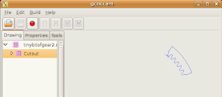
gCNCCam for generating the G-code, and EMC2 for controlling the machine.   Inkscape saves to DXF, which can be loaded by QCad so I loaded my gear directly there.  The center is not indicated by Inkscape, but is easily found geometrically, as shown.

gCNCCam has some problems generating a proper entry move, so we use a modified version, available here.

I put a central hole to act as an axis, and a couple others to act as placement points for a Sharpie.   I then drew a large outer gear ring, which would be treated as the outer ring gear.  It was so large, i had to cut it into two parts, to fit on the CNC. I tottled off to the lab to cut it.

Total fail.  EMC2 refused to cut it, and rightly so, since the tool radius was such that many of the corners could not be cut out.  No concave corner can be tighter than the tool radius.  Unfortunately, gCNCCam doesn't complain about this, and its processing for a file of this complexity was very slow.

I manually edited the drawing, to round out the bottoms of the gears.  This process quickly became iterative, and slow.  Heres my advice:
  • Cut out a small piece of gear, gCNCCam will work much faster, and if it will cut one tooth, it will cut them all.  However, bear in mind that:
  • If the G-Code fails, look closely at where.  When I chopped my gear into parts, it was the point where I chopped it that had a tiny concavity, not the tooth itself.  Putting a small round on that corner resolves the problem.
  • Numerical issues can also cause problems.  I've had better luck designing the drawing for a tool with 3.2mm diameter, and telling EMC2 that the tool diameter was 3.199mm.
  • The gCNCCam to EMC2 loop quickly gets tedious, and at first, I was doing the drawings at home, and then heading to Foulab to discover that EMC2 would reject them.  Loading the file in gCNCCam can also be very long. (It seems to do all its work on load, or when a parameter is changed, analyzing the graph then.  Clicking the generate GCode button is anticlimactic, and takes only a moment.)
  • The solution I found was to install a virtual machine with the EMC2 distro, and run the design through at home, before heading to the CNC.  The boring wait for processing could be offset by working on other things.

Its also worth noting, that gCNCCam got inside and outside backwards on the drawing.  So my first attempt at the ring gear had the tool on the inside, with, needless to say, poor results.  gCNCCam draws an arrow in the direction of cut.  If your template is for counter clockwise, but it draws the arrow clockwise, switch the tool from inside to outside.
Use a small piece to work out if the tool can cut it it will be much faster.  Also, watch gcnccam closely, this was supposed to be a counterclockwise cut, but its moving the tool clockwise.  Inside and outside will be reversed.


So after much hand editing, I got it to work.  I cut the gears out of MDF, which can be cut pretty fast, and even then, the cutting time was LONG, over an hour for the ring gear. 

I cut out a 24 tooth inner gear and a 72 tooth outer gear, glued some legs on and got down to drawing.  And this is where those of you who kept reading to the bottom of the post get to laugh at the author.  Thats right - 72 and 24 - so it draws:
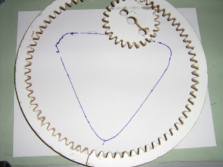
Since 72/24=3 i get a lovely triangle


Twenty-five and 27 tooth inner gears will be coming up shortly, don't worry.  After this, however, I will probably write my own gear drawing code.  The Inkscape renderer looks good, but it has too many concave corners that have to be hand edited.